Lou, thanks for your interest. Yes the entire thing was made purely
with
GRC and there was no modification to the generated Python. All that is
required to run the scanoo_rx GRC file unmodified is a UHD compatible
device and an installation done with “./pybombs install uhd gnuradio”.
Johnathan’s GNURadio Live DVD should work too -
http://gnuradio.org/redmine/projects/gnuradio/wiki/GNURadioLiveDVD .
For reference, here is a screenshot of the scanoo_rx GRC flowgraph -
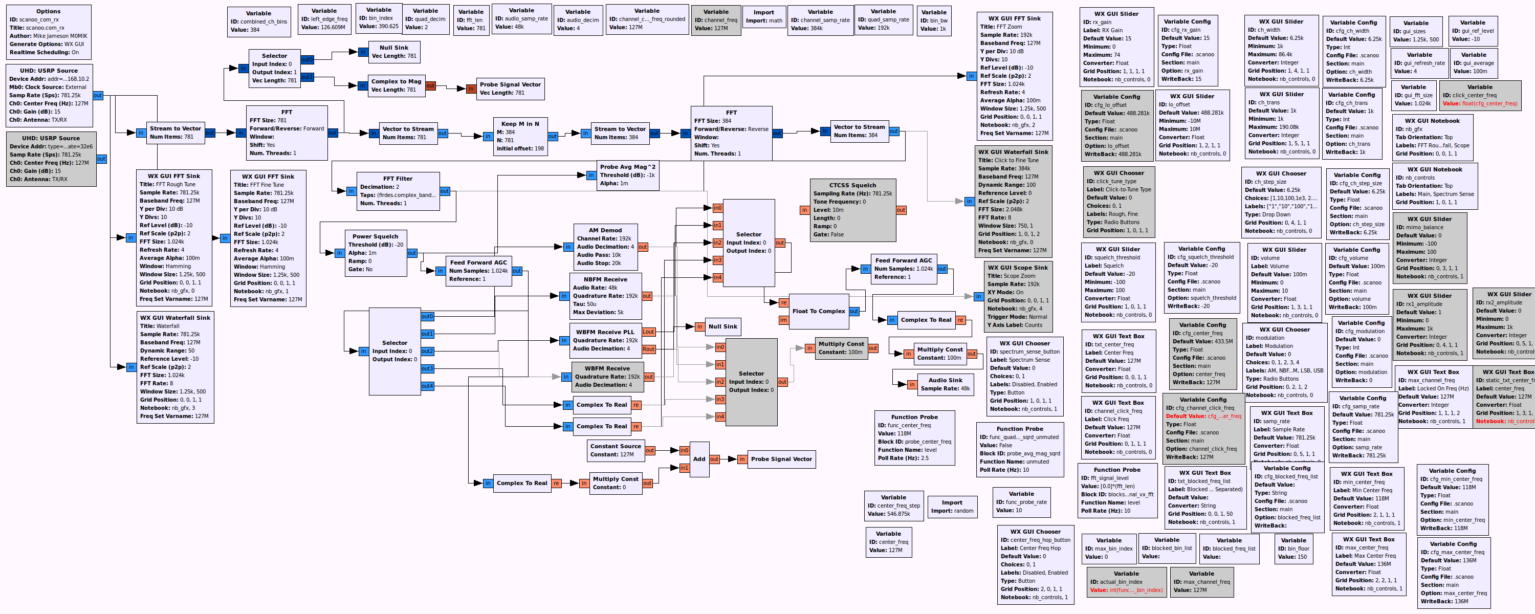
Starting at the top left, the ‘UHD USRP Source’ block receives complex
time
domain samples from your UHD compatible SDR hardware and sends these
complex time domain samples to the ‘Stream to Vector’ block and the
three
‘WX GUI’ display blocks.
The ‘Stream to Vector’ block sends the complex time domain samples in
vector chunks of size ‘fft_len’ to the ‘FFT’ block which outputs the
vector
chunks of complex samples in frequency domain format. FYI, the ‘WX GUI
FFT
Sink’ blocks (aka ‘FFT Rough Tune’/‘FFT Fine Tune’) do this internally
in
order to display the signals in the frequency domain.
The output of the ‘FFT’ block is sent to a ‘Selector’ block which is the
pathway to the ‘Probe Signal Vector’ block used for spectrum sensing.
The
‘FFT’ block also sends samples to a ‘Vector to Stream’ block which puts
the
vector chunks back into a single stream of samples in frequency domain
format.
The ‘Vector to Stream’ block sends the stream of frequency domain
samples
to the ‘Keep M in N’ block which is responsible for picking out the
channel
we want and at the same time it decimates the signal to
‘channel_samp_rate’
in order to reduce the amount of data processing required for blocks
further down the chain. The channel is chosen by either a mouse click
on
the ‘FFT Fine Tune’ / ‘FFT Zoom’ displays or by enabling ‘Spectrum
Sense’
mode. When ‘Spectrum Sense’ mode is enabled, the maximum signal found
is
selected as determined by the ‘Probe Signal Vector’ block.
The ‘Keep M in N’ block sends the selected complex frequency domain
samples
to the ‘Stream to Vector’ block in order for the samples to be converted
back into complex time domain format by the ‘FFT’ block which is set to
‘Reverse’ (IFFT).
The ‘FFT’ block outputs a vector of complex time domain samples of the
chosen channel and sends these via a ‘Vector to Stream’ block to an ‘FFT
Filter’ block. The ‘FFT Filter’ block is responsible for decimating and
filtering the time domain sample stream. The bandwidth of the filter is
adjustable in the ‘Main’ section of the GUI controls and can be seen
when
viewing with the ‘FFT Zoom’ display. In the ‘FFT Filter’ block there is
logic to change the filter automatically when the modulation is changed.
AM/NBFM/WBFM use a lowpass filter and LSB/USB use a complex bandpass
filter.
From the ‘FFT Filter’ block the sample stream is sent at a rate of
‘quad_samp_rate’ to the ‘Power Squelch’ block. This squelch block is
responsible for determining whether the chosen signal is powerful enough
to
lock on to. If so, the samples are passed through a ‘Feed Forward AGC’
for
signal level normalisation and then on to the audio demodulation blocks
via
the modulation ‘Selector’ block. The ‘Probe Avg Mag^2’ block after the
‘Power Squelch’ block is used to halt the spectrum sensing and center
frequency hopping in order to lock onto the selected channel. This
‘Probe
Avg Mag^2’ block is also the reason for the signal holding on channel
for a
few seconds after the squelch cuts out. This delay is adjustable with
the
block’s alpha setting.
If there are any queries as to the use of raw FFT bin indexes then I’ll
be
happy to explain that too, such as in the frequency lockout feature.
Mike
–
Mike J. M0MIK BSc MIET
Email: [email protected]
Web: http://scanoo.com