Hello everybody,
I’m trying to do some channel measurements using a setup based on three
PCs with two USRP2 devices (equipped with RFX2400 daughterboards) and
GNU Radio 3.7.
One of the PCs acts as network controller, it creates data the other PCs
should transceive. The network controller therefore iFFT processes some
random data and tells the two daemons what the have to send. If the USRP
of one of the daemons receives something the received data gets
delivered back to the network controller, which FFT processes the data
and does some calculations.
So the GNU Radio action is happening only on the daemons. From the
transmitter point of view it’s just adding the cyclic prefix, on
receivers point of view there is a Schmidl & Cox correlator for
synchronization and a block picking the samples of the payload.
The (i)FFT stuff is happening on the network controller, using NumPys
FFT implementation.
My predecessor (whom I sadly can’t ask) built this communication system
and used a decimation factor of 16 and a FFT size of 64.
Now I wanted to try a different FFT size. I expected this modification
to be straightforward, just changing values and using a proper, low PAPR
preamble.
However, I tried it with FFT sizes of 32, 96 and 128 - still with a
decimation factor of 16 - and had no success. Bit error rates were far
too high (about 40%).
I looked into some log files and found that apparently at least the
Schmidl & Cox correlator and the payload picking block is working, it
catches the frame start and delivers the amount of samples needed for
the FFT. Please notice, as already mentioned above, that I do the FFT
with NumPy on the network controller after transmission has finished.
Now if I compare the post FFT / frequency domain received data with the
sent data, looking at the argument differences I can observe some
strange values:
I would expect a straight line with an slope (which I could correct by
equalizing), as in this figure:

Please ignore the “jumps” by 2*pi (or 360) and keep in mind it’s drawn
using Matlab, this means one-based indexing, therefore ignore subcarrier
17 as it’s the DC carrier.
Instead, I get some random jumps by pi on some of the carriers, as seen
in this figure:
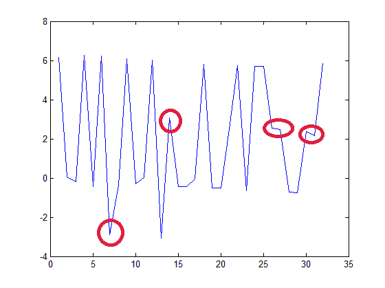
This happens with all FFT sizes I tried except the original FFT size of
64 if I keep the decimation factor of 16.
Now I noticed that there seems to be some correlation with the
decimation factor:
If I choose a decimation factor, so that the ratio between FFT size and
sampling rate is the same as in my original and correctly working setup
(FFT size: 64, decimation factor: 16, so about 100 kHz per subcarrier) ,
everything seems to work properly. The BER is low and comparing the
argument of sent vs. received data I can see the expected line without
any random jumps. This behaviour I could observe with FFT size 32 (using
a decimation factor of 32) and 96 (using a decimation factor of 12) -
with other decimation factors I didn’t work.
Now I’m trying to understand this phenomenon. I expected, that I would
be able to change FFT size without touching decimation factor. At least
I thought that using less FFT bins with the same decimation factor
shouldn’t harm, giving each subcarrier more bandwidth.
It would be great if someone could help me regarding this problem as I’m
quite confused now and don’t really know what to do.


