I am working on a project which requires to receive signals from LEO
satellites like orbcomm and iridium.
I tried to use USRP N210 to collect the data, but I found the signal may
be
too weak to be observed.
Stuffs I used:
USRP N210, DBSRX2 800-2400MHz
Minicircuit cable amplifier, provides 37 dB gain at 15V/0.68A
supply
input. To ensure signal is enough enhanced, I used two of them in recent
experiments.
Horn antenna with frequency range from 0.8 - 18 GHz. beamwidth 60
degree.
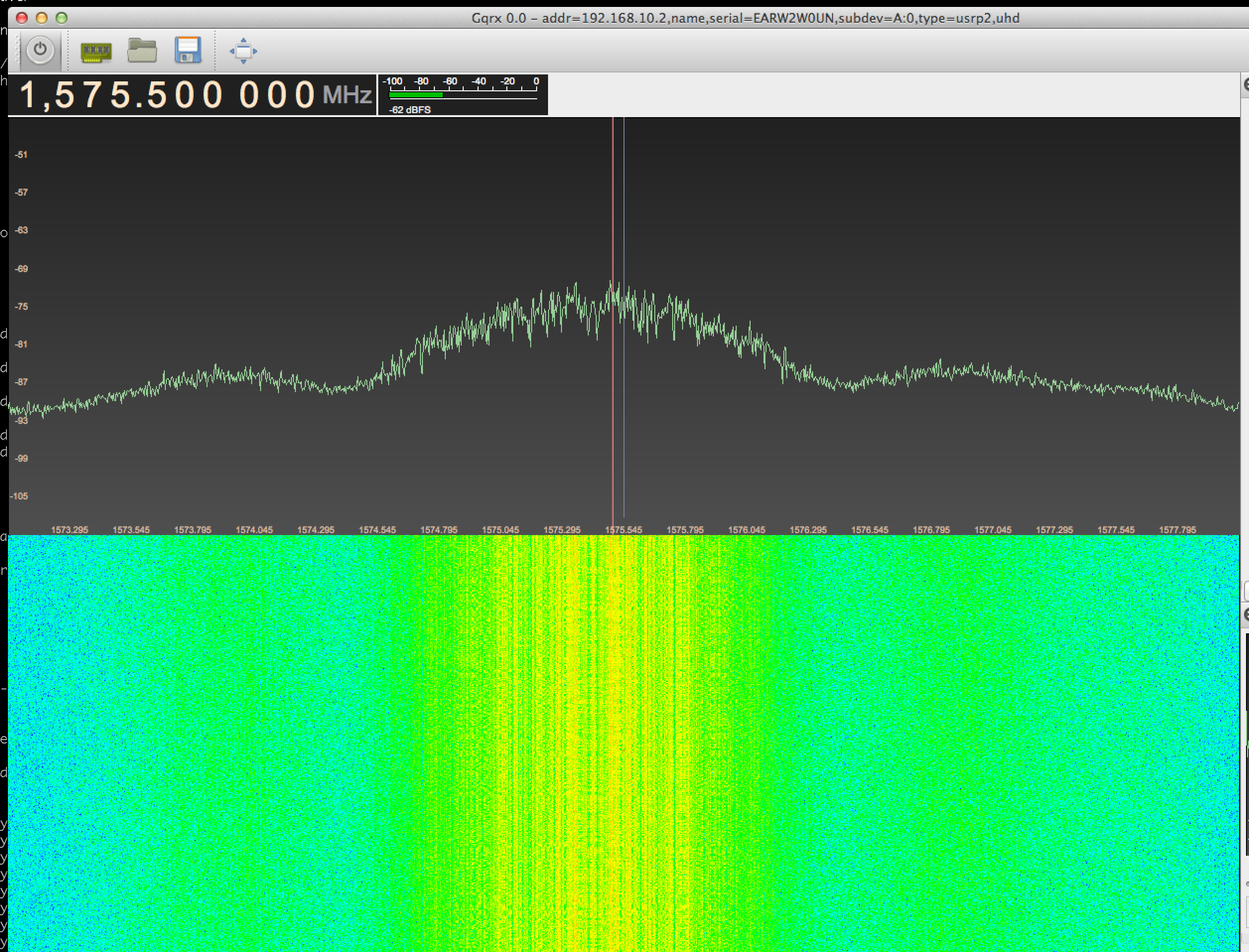
After connected all things and warming up, I run “uhd_fft” to check if
signals can be seen in frequency domain. I expected a peak around the
center frequency. However, it is just noise. But if I turned center
frequency to GSM band, it showed signal clearly. And then I turned it to
1.57542 GHz, which is the L1 band of GPS, it also shows nothing but
noise.
So, I am wondering if it is because the signal it too weak to be
detected
in that way.
Have anyone ever done weak signal detection and collection before with
USRP
? not only satellite, any weak signals is fine.
If you have done similar project before, could you please tell me how
you
know signal is there if it cannot be seen by FFT. Any other function can
help ?
Minicircuit cable amplifier, provides 37 dB gain at 15V/0.68A supply
input. To ensure signal is enough enhanced, I used two of them in recent
experiments.
Horn antenna with frequency range from 0.8 - 18 GHz. beamwidth 60 degree.
You probably want something more directional and a more restricted
frequency range to get more gain.
Also if the satellite signals you want to receive have any kind of
polarization, you want your antenna to be matched to it.
Since they’re LEO and, well, moving you actually might need a tracking
antenna and the software to drive it.
Then you need FILTERS … the most narrow and high selectivity you can
find that fits your frequency of interest.
If you’re trying to listen to very weak sat signals but at the same
time you have only a few hundreds MHz away strong GSM carriers, stuff
if going to saturate with all the gain you’re putting in, so you need
filters.
Finally what’s the exact model of amplifier you used and what kind of
NF does it have ?
And then I turned it to 1.57542 GHz,
which is the L1 band of GPS, it also shows nothing but noise.
Yeah, seeing GPS is not easy, signals are well below the noise floor
AFAIK.
Yeah, seeing GPS is not easy, signals are well below the noise floor
AFAIK.
I would rate GPS as invisible, with normal receiver technology. They are
using a low bitrate, spreaded over a very large frequency range. The
only
way to “see” something should be correlating and decoding the stuff.
I would rate GPS as invisible, with normal receiver technology. They are
using a low bitrate, spreaded over a very large frequency range. The only
way to “see” something should be correlating and decoding the stuff.
I’ve actually seen it without de-spreading during a presentation
recently. Of course it had been received with a 25 m dish or so
apparently someone else was at OHM …
i had not seen the trick of squaring the GPS signal to get rid of the
phase modulation and hence the spread spectrum to only recover the
doppler
shift elsewhere: looks like a great trick to validate the reception of a
GPS
signal even below thermal noise levels.
–
JM Friedt, FEMTO-ST Time & Frequency/SENSeOR, 32 av. observatoire,
25044 Besancon, France
i had not seen the trick of squaring the GPS signal to get rid of the
phase modulation and hence the spread spectrum to only recover the doppler
shift elsewhere: looks like a great trick to validate the reception of a GPS
signal even below thermal noise levels.
Me either, it was the first I heard of it and I need to give it a shot
sometime !
This is like a hard comparison; you can’t really compare the two.
Howver, both have an ADC. GPS receivers usually have correlator banks to
detect the signal, yielding a large processing gain by effectively using
half eternity of energy.
This is like a hard comparison; you can’t really compare the two.
Howver, both have an ADC. GPS receivers usually have correlator banks
to detect the signal, yielding a large processing gain by effectively
using half eternity of energy.
Well, presumably projects like Redirecting… are using
one or more correlators, but in software, rather than hardware.
Ruoyu,
First off, Singapore is a very noisy place (From a radio perspective),
so you are going to have to pair any external low noise amplifiers with
appropriate filters for your signals of interest. It is vital that none
of the components in the radio signal chain receivers too much power
which can lead to non-linearity and ultimately to damage to the radio.
Placing a very high gain amplifier such as you have, in conjunction with
a wide band antenna is not a safe proposition with a USRP daughter
board, other loud and local signals will overwhelm the initial analog
stages of the radio. I find even when using a dish pointed skywards in
an urban area that introducing a wideband LNA without a filter causes
other local cellular (etc) signals to saturate my USRP frontend.
When I’m working with satellite signals close in frequency the Iridium
signals you are interested in (~1.6GHz) I use a combination of a
Minicircuits ZX60-242GLN-S+ LNA and a NBP-1560+ bandpass filter with
good results with a variety of USRP’s/daughter boards. For weather
satellites in the 137MHz band (which is the same band as the Orbcomm
downlink) I use a custom LNA+filter from SSB in Germany. In both cases
gain is approximately 30dB and the noise figures very low, typical
numbers for LNA’s ideal for satellite use are 0.4-0.8dB NF.
You should rethink your antenna(s) completely, Orbcomm use a right hand
circular polarized signal for their downlink and you could thus use any
antenna design that was intended for use to receive NOAA’s APT weather
satellite signal you will find many references on how to build these if
you google “APT antenna”.here’s one incredibly simple example of a less
than ideal, but simple solution that worked fine: NOAA-19 APT Reception using GNU Radio and a FUNcube Dongle. In fact listening to the APT signal
from NOAA-16, NOAA-18 and NOAA-19 may be a good starting point for you
to develop your skills.
Iridium is also a RHCP signal, and in those bands people typically use a
patch or helix antenna for these types of signal, both can be built
quite easily and at low cost.
You should also familiarize your self with the open source software,
“predict” and “gpredict” (There are others but these are recommended),
as it is important to know when (and where with a directional antenna)
your signal of interest is actually visible in the sky.
And lastly GPS L1…in the last few weeks I happen to have been listing
to this with Balint from Ettus whilst we have been testing some antennas
and other hardware. A USRP nor any other radio is going to see the raw
signal above the noise floor with an omnidirectional antenna, the magic
of GPS is all down to spread-specturm processing gain and is an
interesting study if you have the time. One quick trick is to use
autocorrelation to look for the signals, since the L1 C/A spreading code
repeats every 1mS, it’s relatively easy to prove it’s there even though
you can not see it in the FFT. And if your curious about what it looks
like when you work a little harder to listen to it, then a USRP (SBX in
this case) and a 1 meter dish prove more than sufficient:
Filters will all to some degree attenuate your signal of interest, but
by how much varies dramatically depending on the type and design of
the filter, it could be 0.5dB or 20dB, but the point is that it
attenuates potential interferers and noise by a great amount. An LNA
cascaded into a bandpass filter as close as possible to the antenna is
generally an ideal setup for this type of weak signal work.
LNA into filter is the line-up we use in radio astronomy, which might be
described as the “limiting case” of weak-signal work.
A circular-waveguide feedhorn designed for the band of interest will act
as a high-pass filter with a “knee” at the design frequency of the
feedhorn. This,
combined with directionality of a dish is often enough to eliminate
the worst of the interferers before the LNA, and then apply a filter
after the LNA.
Ruoyu,
Buying a commercial Iridium antenna is, I’m sure, an ideal solution for
your work.
If the antenna is entirely passive (i.e it has no LNA and filter built
in) then it will still pick up frequencies outside the band of interest.
And, though attenuation will increase as these environmental signals get
further from the Iridium frequency band, strong local signals will still
likely be received at a signal level much stronger than the Iridium
signal because their path loss is so much smaller.
I suggest to you that you take a tool like gqrx or a grc flow graph and
just move an FFT through all the spectrum supported by your daughter
card, you’ll get a basic feel for what your local RF environment looks
like through your antenna of choice. I suspect that as soon as you get
into 1.8GHz you will see a lot of strong broadband signals from cellular
equipment. I know I also see some narrow band terrestrial signals in the
1.6-1.7GHz band locally in the US.
Filters will all to some degree attenuate your signal of interest, but
by how much varies dramatically depending on the type and design of the
filter, it could be 0.5dB or 20dB, but the point is that it attenuates
potential interferers and noise by a great amount. An LNA cascaded into
a bandpass filter as close as possible to the antenna is generally an
ideal setup for this type of weak signal work.
for those folks interested in GPS (and Galileo) signal processing with
USRP+DBSRX and GNU Radio related stuff, please take a look at the
publications available at Redirecting…
We use three VOLK-based correlators for GPS L1 and five for Galileo. An
active antenna is also desirable, but any cheap ($20) commercial part
should work well.
Best regards,
Carles
This forum is not affiliated to the Ruby language, Ruby on Rails framework, nor any Ruby applications discussed here.